| The Ford Escape Hybrid was offered for sale as a 2005 model. At the start of production for the 2006 model year the Mercury mariner was added. At the start of production for the 2008 model year Mazda acquired this same vehicle as the Tribute. The hybrid systems used in all three of these vehicles are identical. Because Ford Motor Company designed the all wheel drive model with a separate PTU unit, the FWD and AWD transaxles are the same. The hybrid battery pack is one of the most powerful in the industry rated at 330 volts and is located under the cargo cover. |
The transaxle is known as the eCVT or the P310 and has a dedicated cooling system that is separate from the engine cooling system. The hybrid cooling system uses a 12 volt electric pump to circulate the coolant. The P310 uses a Power Split Device (PSD) similar to the Toyota Prius to allow the transaxle to operate in its various driving modes. Unlike the Prius the P310 does not use a chain to connect the drive motors to the final drive. Instead, it is gear to gear. A four cylinder gasoline powered engine along with two 3 phase AC electric traction motors power the vehicle. The engine uses stop/start technology at which time the electric starter motor will start the engine if needed. The engine is a 2.3 Liter Atkinson Cycle design and can maintain a low RPM range while meeting the necessary torque requirements.
The vehicle can launch on electric power only. It also utilizes a regenerative braking system to recharge the hybrid battery pack and has electric assist steering which is functional when the ICE is off.
Power units, the Transmission Control Module (TCM), the DC to AC voltage inverter and the high voltage capacitors are all contained inside the transaxle. All other hybrid electronic controls are externally located.
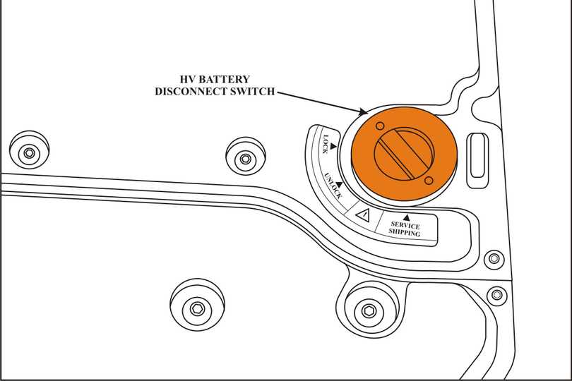
| Next, Locate the ORANGE HV Battery disconnect switch in the right rear corner of the cargo area. Next, rotate the cover to the “UNLOCK” position and pull it out. Do not stick your hand or drop anything in the hole, the 336 volt battery pack is below the opening! Next, replace the cover in the “SERVICE SHIPPING” location. Wait 5 to 15 minutes for the HV capacitors to discharge and then using your CAT III voltmeter and Class zero rated rubber gloves, check the HV circuits to make certain the voltage level is below 12 volts. Remember to wear your insulated gloves until you are sure there is little or no voltage on the high voltage circuits. |
Caution: even though the capacitors are discharged, the hybrid battery pack is always lethal!
Once the hybrid battery disconnect switch has been turned off, it will be necessary to verify with class zero rated rubber gloves and a 1000 Volt, CAT III DVOM that the high voltage has dissipated
This is done at the HV Battery cable connection in the battery box.
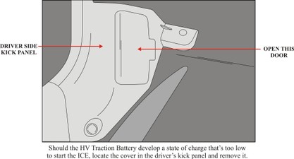
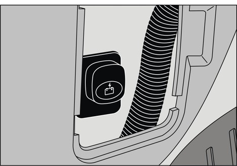
Behind the door is a Battery Charge Switch. Pull the knob out and wait 8 minutes for the vehicles 12 volt battery to provide just enough power to start the ICE, let the vehicle run long enough to charge both batteries. There is an 8 minute timer that will shut the switch off. This was eliminated in 2009.
The High Voltage Traction Battery is cooled by fans as the fresh air is drawn in through the driver’s side rear quarter window vent. Battery fumes are exhausted through the bottom half of this same window vent. There is a small removable panel on the intake side of the duct work just below the window inside the vehicle. Located behind that panel is a filter that will need to periodically be replaced.
The High Voltage Traction Battery uses two cooling fans which also require periodic cleaning. The fan duct work is connected to the ducts that lead to and from the window vent.
There have been incidences of when pressure washing the vehicle, water may be forced down both the intake and exhaust ducts and into the high voltage battery area. This obviously causes major damage resulting in very expensive repairs.
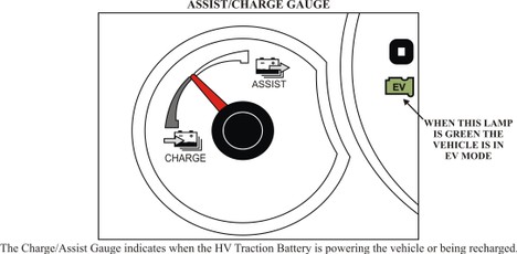
Figure 1
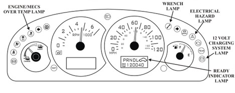
Figure 2
When the EV lamp is green the vehicle is in EV Mode
Hybrid Warning Lamps and Monitor
The “Wrench” Lamp illuminates when a malfunction has occurred. The “Triangle” Lamp illuminates when a serious malfunction in the hybrid system occurs. If the “BATTERY” Lamp is illuminated, this means the 12 volt system has a malfunction. When the “READY” Indicator Lamp is illuminated, this indicates that the vehicle is ready to drive even though the ICE may not be running. When the “Engine/MECS Over Temp” Lamp is illuminated, there is an over heating condition in the ICE or the hybrid cooling system.
The Ford Escape Hybrid can exhibit a variety of driving modes as well as a failsafe mode. Theses driving modes are controlled by the Vehicle System Controller System (VSC) which consists of the Powertrain Control Module (PCM), the Transaxle Control Module (TCM), and the Traction Battery Control Module (TBCM) which communicate over a CAN Bus network. The PCM contains the VSC program and is responsible for controlling the hybrid system as well as the failsafe and code storage operations. Hardware used consists of a traction motor battery, two traction motors located inside the transaxle and a power split device. These are the most common components seen in series parallel hybrid systems. All of which produce the following driving modes:
• Electric Mode
• Creep Mode
• Positive Split Mode
• Negative Split Mode
• Neutral Gear Mode
• Engine Cranking Mode
• Limited Operating Strategy Modes
Inside the transmission there are two Motor/Generators. One is referred to as the Generator Motor while the other as the Traction Motor. The power split device is nothing more than a planetary gear set which connects power from both the Internal Combustion Engine (ICE) and the generator. The Traction Motor connects to the drive wheels. There are no clutch packs inside this transmission.
The “Electric Mode” is when the vehicle is driven by the Motor/Generators only known as the EV Mode. This “Electric Mode” is also used for reverse movement because the engine can only deliver torque in a forward direction.
The “Positive Split Mode” is when power from the ICE is split between the generator motor and the path to the drive wheels. Depending on need, the generator motor can charge the HV Traction Battery or power the traction motor through the power split device. This mode also allows the traction motor to operate as a motor or as a generator if it needs to make up the difference between engine power and desired power at the drive wheels.
“Creep Mode” is when the PCM Commands a predetermined amount of torque to the drive wheels via the ICE, Generator Motor or Traction Motor to mimic the creep normally found on vehicles equipped with a torque converter. The maximum creep speed in forward or reverse is approximately 4 MPH (6 km/h).
The “Negative Split Mode” occurs when the ICE is running but the generator motor is reducing engine speed. This is not a preferable mode but occurs when all of the following vehicle conditions are met:
• The engine is running
• Vehicle speed is high
• The high voltage traction battery is charged
• Reducing engine throttle is not desired
When Neutral is select, the “Neutral Gear Mode” simulates neutral by not delivering any positive or negative torque to the drive wheels. There are two neutral operating states:
1. Active neutral activated above 6 MPH (10 km/h).
In active neutral, the generator motor is allowed to start and stop the ICE as needed to maintain the HV Traction Battery charge and provide HVAC operation.
2. Passive neutral activated below 6 MPH (10 km/h).
In passive neutral, the engine must remain in the state it was when the mode was entered and is not permitted to change state, (start or stop).
If the engine is running when entering passive neutral, the speed control of the engine is transferred from the generator motor to the engine itself.
The engine controlling its own speed in passive neutral is described as “Secondary Idle”. The vehicle cannot be started in passive neutral, but can be started in active neutral.
The “Engine Cranking Mode” is when the generator motor inside the transmission rotates the ICE to a speed of approximately 1,000 rpm’s for about 0.3 seconds. At which time the PCM commands fuel delivery and spark appropriately to start the ICE.
Should one or more problems arise with the engine, transaxle, traction battery or regenerative brake systems, the “Limited Operating Strategy (LOS)” goes into affect. The intention of the LOS modes is to manage vehicle operation after one or more of these systems have failed. The PCM will initiate the proper LOS mode based on the severity of the malfunction detected. Some LOS modes will provide a limp home condition while others may totally disable the vehicle. A corresponding DTC will be stored however; the root cause that initiated the LOS mode may be in a different subsystem or component than indicated by the DTC. The diagnostic tip here is that the code does not necessarily indicate a failed subsystem or component as much as it indicates the subsystem or component that is affected by the LOS mode.
The “Normal Power Down Sequence” is conducted by the PCM. Modules that are powered up by RUN circuit immediately shut down when the ignition is turned to the OFF or ACC position. The exception to this is with the PCM, TCM and TBCM (Traction Battery Control Module). They stay on until their power down sequence is complete.
The “Regenerative Braking” strategy occurs when the driver applies the brake. The PCM calculates how much negative force can be applied through the traction motor to transparently assist in the breaking effort. This negative force is then used to capture and store a portion of the energy which would normally be lost as heat during a braking event. Depending on the state of charge of the high voltage traction battery, the amount of negative torque provided by the traction motor can vary between 0 and 100 percent turning the traction motor into a generator as it charges the HV batteries.
If you found this quick tip to be helpful, let us know below. If you need technical help from one of our tech experts, give us a call at 1-800-245-7722 and we will be more than happy to assist in getting that job done and the customer out the door!


