Finding The Torqshift Difference
Whether you have a 2-wheel drive or 4-wheel drive vehicle equipped with a 6R140 (commonly referred to as the Torqshift 6), there is only 1 valve body listed for this transmission. This is a question that is often times asked on our technical hotline as the 2 wheel drive uses a lube pipe for the extension housing bushing while 4 wheel drives do not. The port opening at the solenoid end of the valve body where the lube pipe is fitted remains open with the 4-wheel drive version. For this reason some have assumed that there is one valve body for a 2-wheel drive and another for 4-wheel drive applications. The lube is fed to this port through a .041-inch orifice in the spacer plate. If there is no pipe it will simply dump into the sump. With 2-wheel drive applications the pipe is inserted and extends to the rear of the transmission where it is the routed to the extension housing bushing.
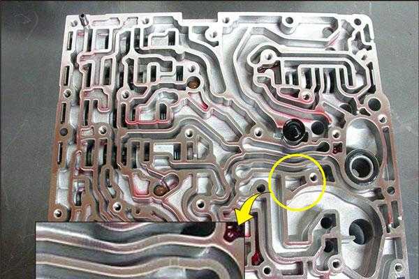
Figure 1
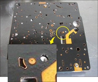
Figure 2
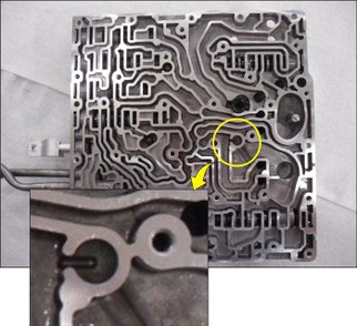
Figure 3
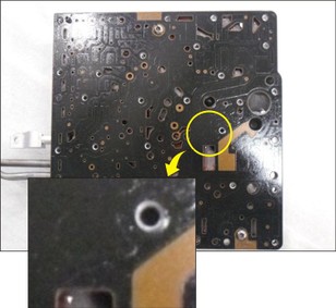
Figure 4
That aside, the main reason for this newsletter is to make know of three different variations of valve bodies we have encountered through the years. Ford does not ever mention two of them, but they are out there. Two of these valve bodies contain only two check balls while the one Ford mentions has three.
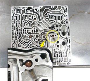
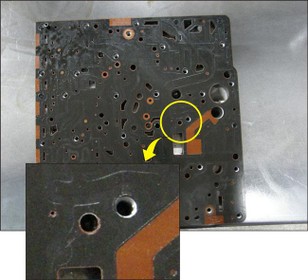
The two types of valve bodies, which contain 2 check balls seem to be very early designs. Figure 1 shows what I believe to be the earliest design of all three-valve bodies. The critical area to be observed is displayed in the call out part of the photo. Figure 2 is the accompanying spacer plate. Notice there are two holes in the spacer plate that fits over the empty pocket shown in Figure 1.
Figure 3 shows the second type “2 check ball only” valve body. But this one I believe shows a transitional phase to where a third check ball will be added. Figure 4 shows the accompanying spacer plate. Notice it no longer has any holes over this area.
Figure 5
Figure 6
Figure 7
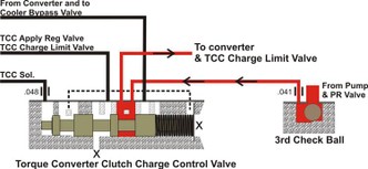
Figure 5 now shows the valve body, which does contain the third check ball. Figure 6 shows the accompanying spacer plate. Notice it now has two holes over the area of the check ball. Figure 7 is a hydraulic schematic reflecting the addition of this .375” diameter check ball. Regulated line pressure coming directly off the pump and Pressure Regulator Valve comes in over the top of the check ball. This pressure is then forced through a .041 orifice in the spacer plate and routed to the TCC Charge Control Valve. From there it becomes Converter Charge Pressure.
With thinking there is only one valve body for this transmission when there are actually three that I am aware of, part interchange can and will cause converter charge issues. Just by looking at the spacer plate shown in Figure 4, if it is used on the valve body with the third check ball shown in Figure 5, regulated line pressure will be blocked from entering the check ball pocket. This means no converter charge pressure, which means a no move condition. You may feel an engagement as the pump and PR valve is able to supply clutch pressure but there will be no turning of the input shaft with an empty converter. There will also be no cooler flow, which might be your clue to this unexpected mismatch of parts.
If you have found this blog post to be helpful, feel free to comment below and share this information with others.


