A 6-Speed from Korea?
| Hyundai and Kia manufacturers use a front wheel drive 6-speed transmission in many of their vehicles. We will this transmission and issues that could be encountered. |
Hyundai and Kia 6 Speed Transmission
The name for this transmission is determined by the size engine it’s paired to. From as small as a 1.2L engine to as big as a 4.0L, the names begin with A6GF1, increasing to A6MF1 and 2, and then to A6LF1, 2 and 3. Similarly, as engine size increases, so does the size of the transmission. This of course is due to the necessary increase in toque capacity. The general application of these transmissions is as follows and is not limited to:
|
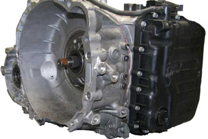
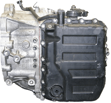
| A variation of this little 6 speed can also be found in late model Dodge Dart 2.0L and 2.4L vehicles (2012 and up), which in this application is called the 6F24. In Hyundai and Kia vehicles this would be the A6MF1 transmission (many thanks for the good folks at ALTO for the use of this transmission). |
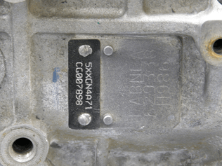
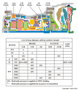
| In some instances, on the transmission there is a tag riveted to the case with the vehicle identification number on it. Alongside this tag, etched into the case is a transmission number. This many times is very difficult to see. If it is readable, and the identification number begins with the letters NA, it is the A6GF1, BA, it is the A6LFx transmission. EA or FA will be the A6MFx. The number etched into the case shown is FABNEA which identifies it as an A6MF transmission. With all these different names, when it comes to Hyundai and Kia, this transmission is simply referred to as the A6 transmission. A component application chart is provided for this nicely compacted transmission. Three brake clutches, two driving clutches and a one way roller clutch are used to operate three planetary gear sets to obtain six forward ratios (speeds) and one reverse ratio (speed). |
| One nice aspect to this transmission from a diagnostic standpoint is that there is a pressure tap for each clutch assembly. Converter clutch apply and release taps are also available between the side pan and the converter housing. These can be easily identified with the typical case embossments next to the taps with letters DR and DA for Damper Release and Damper Apply.
Two reducing pressure taps are also available by the back cover. These two taps can be identified with RED 1 and RED 2 case embossments. The pressures observed on these taps are pressure supplied to the solenoids and pressure switch valves (PSV) in the valve body. RED 1 is solenoid supply pressure to shift solenoids A and B and the PSV’s while RED 2 provides supply pressure to all remaining solenoids. Most times the embossment will only show RED for each of these taps. When this is encountered, remember that the RED 2 tap is closest to the OD tap on the rear cover. |
| What makes these tap nice to have is that the valves which provide these pressures are prone to elongating their bore. This will cause unstable supply pressure to the solenoids and PSV’s producing either solenoid performance codes or gear ratio codes. Dodge offers up pressure specifications for these two valves with their 6F24 transmission. RED 1 is 73-75 psi max and RED 1 is 79-81 psi max. Making a quick pressure check on these taps can give you your valve body’s state of health before pulling the unit or the valve body.Another nice aspect to this transmission is the ability to perform TCM re-learn procedures. Other than the first to second shift, all other shifts are synchronized. This makes TCM re-learn critical towards having quality clutch to clutch shifting. When shift shock or flare occurs, or parts related with the transaxle are replaced, TCM learning should be performed. |
In the following cases, TCM learning is required:
1. The Stop or Stationary learning procedure re-learns garage shifts into gear. With foot on the brake and 0% throttle opening, shift into Neutral for 3 seconds. Then place the selector lever into Drive and hold for three seconds. Repeat this shift pattern four times or more all the while keeping your foot on the brake. 2. The Drive learning procedure is as follows:
Repeat the above driving pattern four times or more. |
| In November of 2015, we published a blog post called “What Happened to the Dipstick?” It discussed how many transmissions are no longer equipped with a dipstick. This is one of those transmissions. In the lower left corner of the side pan is a fill and check lever plug. If the transmission has been drained, the following is the factory ATF Level Inspection procedure:1. Add approximately 5-qts of Kia Type-4 ATF.
2. Using the GDS (or scanner), select vehicle; then A/T menu; then Current Data, and then Oil Temperature Sensor. 3. Run the vehicle long enough to warm up ATF to approximately 122-140°F (50-60°C). 4. Depress the brake pedal and move the shift lever into “R”, “N” and “Drive” and then back, pausing 2 to 3 seconds in each gear range. Repeat this procedure two times. 5. Move shift lever to “Park”, leave the engine running, and then lift up vehicle on hoist. 6. Remove the splash shield under the automatic transaxle. 7. Remove the oil level plug. ATF level is correct if the ATF flows out in a thin steady stream. If no ATF flows out, go to step 8. 8. If ATF flow does not occur, add Kia Type-4 ATF via the oil level hole until ATF flows out in a thin steady stream. Adding ATF: Use a suction gun or equivalent tool to add ATF. Suction guns are available from various tool suppliers. 9. Reinstall the oil level plug and torque to 25-32 lb-ft (34-43 Nm). |
| Alternate ATF Filling Procedure:
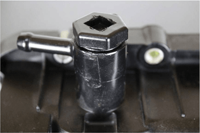
If a suction gun or equivalent tool is not readily available, locate the Vent Eyebolt on the top of the automatic transaxle oil pan (Figure 5) near the battery. Remove the Vent Eyebolt and add Kia Type-4 ATF via the opening. Reinstall the Vent Eyebolt (verify that the gasket is okay and torque to 29-32 lb-ft (39-43Nm). Use only Kia approved ATF meeting Type-4 specification. Using the wrong ATF type may result in degradation of shift quality, or may cause durability issues. Full fill typically is 8.24 qts (7.8L); 1 quart of ATF-SP-IV (part # UM090 CH042) list for about $15.00 dollars. You may have noticed that transmission fluid temperature plays a major role in checking both fluid level and with re-learning the TCM. Should the temperature sensor be defective providing incorrect data, this will negatively affect both procedures. |
There is an O.E. technical service bulletin (#043 [Rev 2] 02/25/2013) that speaks about defective oil temperature sensors producing TFT codes P0711 (Rationality), P0712 (Circuit Low) and/or P0713 (Circuit High). The replacement part # is 466386 3B000.
|
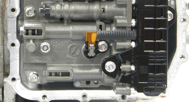
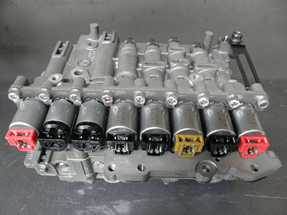
Be sure the TFT sensor is working properly before performing any producer that is dependent upon it. It may be helpful to own a laser temperature gun to compare what it says to the parameter displayed in the scan tool. If the TFT sensor needs to be replaced, it is located on the valve body as seen in Figure 6.Another issue that comes up every now and again is a Torque Converter Clutch Circuit Performance or Stuck Off code P0741 code setting in memory. This typically is a bad solenoid. To avoid any confusion, some literature and/or scan tool will refer to this solenoid as the DC solenoid for Damper Clutch. It is the solenoid to the very right as seen in this photo. |
| This is a Normally Low variable force solenoid. Without operating the solenoid, it does not send hydraulic pressure to its associated valves (TCC Pressure Control and Shift valve). As it is duty cycled, it controlled signal pressure works on these valves to smoothly apply the converter clutch. As it is being commanded to do so, the computer is comparing engine rpm (ERPM) with the input shaft rpm (ISS) to control the rate in which the clutch is applied. Once it is fully applied, both rpm readings should be near the same. If these two rpm reading do not match when full apply is commanded, P0741 sets. Again, this typically is due to a mechanically failed solenoid. It can also be stuck valves, bad rings or torque converter. Should a new converter clutch solenoid be needed, there are two different part numbers. If the transmission being worked on is using a steel side oil pan, it takes a 46313 3B673 solenoid. If it has a plastic oil pan, all A6LF transmissions will use this same solenoid. But the A6GF and the A6MF style transmissions with a plastic pan uses solenoid part number 46313 3B073. |
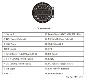
| If P0743 sets for electrical problems, this solenoid measures approximately 5 ohms and ranges between 50 to 850 mA. Figure 8 provides terminal identification for the transmission’s pass through connector. Pin 10 is the power supply for the TCC solenoids and is ground controlled through pin 2.If checks are to be made at the computer, refer to factory wiring diagrams. With the transmission being in a variety of platforms, the transmission is controlled by one of three different computers. As a result, the TCM/PCM makes can be Kefico (TCM), Delphi (PCM), or Continental/Siemens (PCM). |
| If you have found this article to be helpful, let us know. Comment below and share this article with others!Looking for automatic transmission tech manuals that cover – rebuilding, diagnostics, code, valve body, checkball locations and much more? Check out our bookstore will you will find what you are looking for! |


